
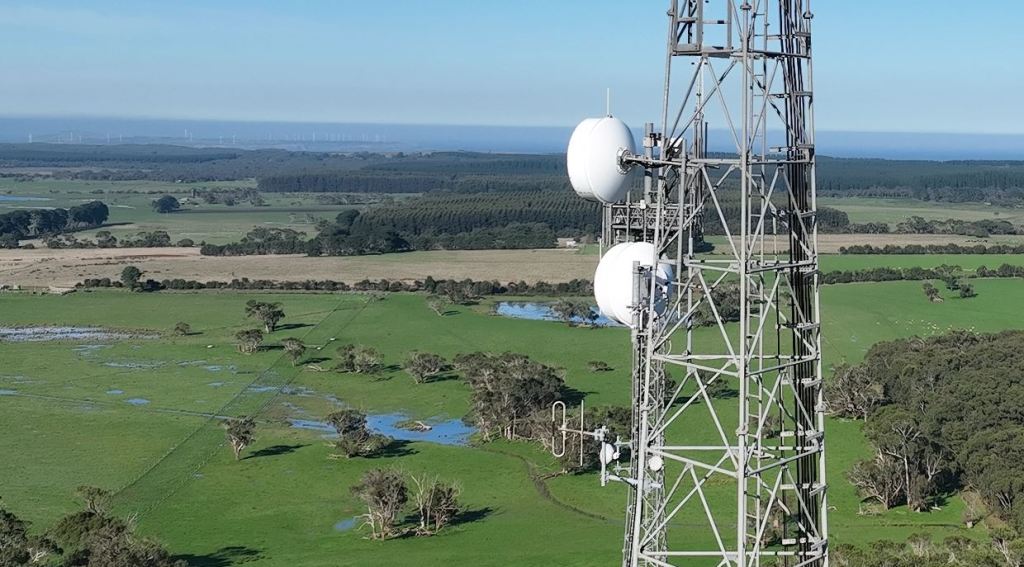
Have you ever tried to commission a point-to-point radio link and found that it won’t work properly because the radio path is obstructed?
It can be a bit of a disaster if the project is ready to be commissioned and then the riggers install and pan the antennas only to find that the expected results cannot be achieved. This will then be followed by a flurry of activities to find out why it doesn’t work and what can be done about it. If you’re in luck the antenna height can be raised to avoid an obstruction. This may be easy, but it could involve additional negotiations with the tower owner and the end-user. Lots of delays and additional costs for new antenna mounts, replacement cables and installation effort. Worst case, you might have to change the network and link topology to find new radio paths that will satisfy the user’s requirement. Clearly it is better to be prepared with a link that has been surveyed and that has adequate clearance for the foreseeable future.
The link owner also cannot avoid these link clearance issues. Unfortunately, line of sight is not always guaranteed, even if it was perfect when the link was designed and installed. Trees grow, new buildings get constructed and these will slowly start having a negative impact on your link until it fails.
What is radio line of sight and how do we test a proposed link to see if it will work?
A radio link needs a clear view from one side of the link to the other. The level of clearance required depends on the link characteristics such as the carrier frequency and link distance. Some links will work with a limited number of obstructions in the path but losses will quickly add up to make the link unworkable. Sometimes diffraction losses can be made up by increasing the antenna gain but this leads to other issues such as tower loading due to wind loads as well as higher costs.
In the end a good design is a balance between the link requirements and all the physical link elements to meet the link performance objectives. VHF and UHF point-to-point links are relatively low cost for the transfer of low data rate services over a few km’s. High-capacity microwave links could be required for critical infrastructure or emergency services over distances exceeding 60 km. The design principles are the same for both link types and must be addressed in the link design stage.
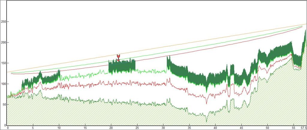
- A path profile is a graphical representation of the terrain between the two antennas with all significant clutter such as trees and buildings indicated on the profile. The line of sight is indicated on the profile with a fresnel zone. A large percentage of this zone needs to be clear and above any obstructions on the radio profile. The size of the fresnel zone is a function of the link frequency and distance.
- Due to the changes in the atmospheric refractivity gradient along the radio path, the radio waves do not travel in a straight line but bend down towards the earth slightly. Over short links this is not a major concern but on longer paths it can become a major design constraint. The k-factor is the ratio between the effective and actual Earth’s radius and has a median value of 1.33. The link should be designed to work over a range of k values to ensure that it will stay operational in varying climatic conditions.
- Rainfall impacts all links but is especially important above 10 GHz. Choosing vertical polarization will typically reduce rain attenuation.
- Link obstructions in the path will result in losses due to diffraction of the radio waves at the obstruction. The type and number of obstructions will have an impact on the size of the loss.
- In some cases, in longer links over flat terrain, the radio waves can be reflected and cause a loss at the remote receiver. This is one example of multipath propagation conditions that should be evaluated for microwave radio links.
- Diversity techniques can be used to avoid or compensate for specific propagation issues on a link. It is obviously preferable that these techniques are identified in the original design as it may be difficult or disruptive to add it to a problem link afterwards.
- All the link design parameters are entered on a link planning tool to determine the typical link availability. This is normally defined as a percentage, for example 99.999% results in a link that will be unavailable due to propagation issues for 315 seconds in a typical year.
Fresnel Networks is a small and independent consultancy in Adelaide, operating from 2009 and working with network operators to design and develop their microwave radio networks across South Australia. Some of these networks transport critical voice and data for emergency services and high voltage power supply. With around 36 years of experience in microwave radio networks, we can assist any organization that needs to determine if their radio network will operate as expected.
Line of sight surveys are performed by Fresnel Networks as follows:
- Desktop analysis of the link, identifying the major elements, locations, terrain type, clutter and profile on a 1-arc second digital terrain model and satellite photography where available.
- Use the customer’s preferred radio equipment data to create an accurate model of the link. Evaluate link viability and identify issues to be investigated on site.
- Site visit to confirm all relevant link data such as tower coordinates, allowable antenna heights, details of all link obstructions including coordinates, heights and type. All high points and vegetation on the link are included in the site visit where possible. Photos are taken to provide proof of line of sight.
- Completion of the link model and preparation of a line-of-sight report to the client with all relevant detail and recommendations.
